Guide Specification For
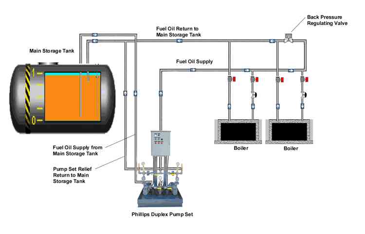
Boiler Loop Duplex Pump Set
|
|
2.01 DUPLEX PUMP SETA. Provide and install a factory assembled "Packaged" Duplex Fuel Oil Pump Set. The set shall have all components mounted on a steel base support fabricated of 3/16" steel plate with 3" steel side rails sealed to form a containment basin with 1/2" NPT plugged drain connection. Containment basin shall encompass the entire perimeter of the duplex pump set and no components or factory piping shall overhang. Pipe shall be schedule 40, ASTM Grade A-53 black steel pipe with A-105 forged steel socket welded fittings and A-105 150# forged steel flanges. Pump sets which have threaded fittings and unions will not be acceptable. (Option: Provide a leak sensor in the Pump Set Containment Basin to shut off the pumps and energize an audible and visual alarm should a leak be detected. The level sensor shall be float operated with covering shroud to protect switch from damage or accidental tripping.) System shall be as manufactured by Phillips Pumps LLC, Bridgeport Ct., Part Number DP-XXX or approved equal. B. Provide one UL listed (1) duplex oil strainer, sized to produced less than 1/2 PSI pressure drop, through a clean brass strainer basket with the maximum anticipated flow. Strainer shall be of one piece cast iron and come complete with level wrench handle. C. Provide two (2) fuel oil pumps with viton seal, each with a capacity of not less than ___ GPH @ ___ PSIG discharge pressure when operating with No. 2 oil. Each pump shall be close coupled to a ____ HP, ____ RPM totally enclosed fan cooled motor, capable of operating on ____ volt, ___ phase, 60 HZ electrical service. D. Provide two (2) fuel oil pump relief valves in each pump discharge line sized to relieve the full flow of the pump without causing the pump motor to overload or any component's pressure rating to be exceeded if the discharge is inadvertently turned off. Valves shall be piped from the system to the return line in the field according to NFPA 30. Pumps with internal relief valves are not recommended. E. Provide two (2) in-line, check valves with metal-to-metal lapped seat and 316 stainless steel springs. Check valve is to have a minimum of 1/2 PSI cracking pressure and to be located on the discharge side of each pump. F. Stainless steel ball valves with carbon steel class 150 socket weld ends, shall be provided on both the suction and discharge of each pump to provide for pump isolation for service. Valve shall include lockable handle so pad lock can be applied to prevent accidental closing or opening if pump is removed from service. G. One (1) 2 1/2" compound gauge shall be provided on the suction side of system. Gauge shall be liquid filled to dampen pulsation, with bright finish stainless steel case, brass movement, and bronze bourbon tube. Gauge shall read 30" vacuum - 30 PSIG and shall be mounted with isolation ball valve. H. Two (2) 2 1/2" dial pressure gauges to be placed on discharge side of each pump. The gauges shall be liquid filled to dampen pulsation, have bright finished stainless steel case, brass movement and bronze bourbon tube. Gauge range shall be based on the fuel oil system operating pressure and shall be mounted with isolation ball valves. I. Provide a time delayed flow sensing switch on the discharge of the pump set to bring on the lag pump should the lead pump fail to maintain flow. Flow switch shall be vane operated to activate a single double throw snap switch. Switch will be wired back to the main control cabinet for alarm and annunciation for lead pump failure. J. Install in the oil return line a back pressure regulating valve, ____" NPT, bronze body with viton diaphragm and disc, to maintain a ______ to _____ PSI pressure range. K. Provide pump set mounted system control cabinet to monitor and control the fuel oil delivery system in response to system demand. Cabinet shall be completely pre-wired, tested and shipped as an integrated system to insure jobsite reliability. Control strategy shall be microprocessor based and utilize a PLC (Programmable Logic Controller). Relay logic is not acceptable. Cabinet enclosure shall be constructed of a minimum of 14 gauge steel, continuously welded and constructed to NEMA 3R standards. Cabinet interior and exterior shall be primed and finished in a durable chemical resistant enamel suitable for industrial environments. PLC shall have sufficient I/O to accomplish all necessary control functions. The control strategy shall be burned into an EPROM at the factory, and shall be safeguarded against re-configuration by un-authorized / un-qualified personnel. All pump mode switching shall be wired direct to each pump motor starter in order to run the system manually if a processor lost should occur. All cabinet front devices shall be identified by black phenolic labels with engraved white lettering. Cabinet shall consist of but not be limited to the following:
|