Guide Specification For Generator Supply
Day Tank With Duplex Supply Pumps

|
|
|
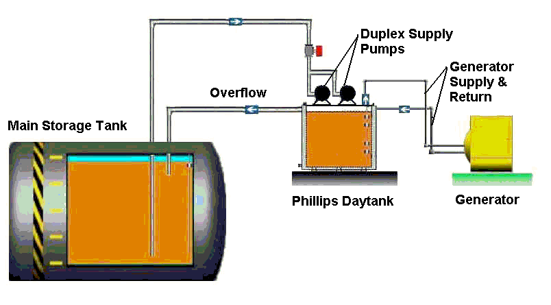
Use the following suggested specification in those mission-critical situations where (2) supply pumps are required and where the main storage tank is below the day tank, and where the fuel can overflow back to the main storage tank via gravity. 2.04 FUEL OIL DAY TANK WITH RUPTURE CONTAINMENTA. Provide a ____ gallon single wall rectangular day tank constructed of reinforced 10 gauge steel, with channel side supports, 1" NPT drain, , 4" NPT inspection/emergency vent ports with cap, visual fuel level gauge, vent port with cap, and a 2" lockable manual fill cap. Tank interior shall be epoxy-coated and exterior shall be finished in an oil-resistant textured enamel. Day tank shall be per UL 142 specifications as manufactured by Phillips Pump LLC, Bridgeport CT, Phone:203-576-6688 B. Tank connections shall include 1" fuel inlets, 1" NPT engine supply and engine return ports, required vent openings, 2" NPT manual fill, and 1" overflow port. Fuel oil supply inlets and engine supply port shall have extended drop tubes to prevent surging in the day tank. C. Provide day tank level control probe arranged to monitor the fuel oil level. Probe shall be designed for installation in the top of the tank to control high-level alarm, supply pumps off, lead supply pump on, low-level alarm/lag supply pump on and critical low-level conditions. D. Provide (2) fuel oil supply pumps with a capacity of not less than ___ GPM @ ___ PSIG discharge pressure when operating with diesel fuel. Each pump shall be close coupled to a ____ HP, 1725 RPM open drip-proof motor. Pumps and motors shall be mounted on tank top and hard-piped into tank top. Each supply pump suction shall include a normally closed solenoid valve which will open when that supply pump is engaged. E. Rupture basin (open top), with 1" drain, shall surround tank with 150% capacity of tank specified. Provide in basin a rupture basin float switch with alarm and pump shut down which functions upon detection of oil in the rupture basin. Rupture basin interior and exterior shall be finished in an oil-resistant textured enamel. F. Provide day tank-mounted system control cabinet to monitor and control the fuel oil delivery system in response to day tank demand. Cabinet shall be completely pre-wired, tested and shipped as an integrated system to insure jobsite reliability and shall be capable of operating on 115 volt, single phase, 60 Hz electrical service. Control strategy shall be microprocessor-based. Enclosure shall be constructed of a minimum of 14 gauge steel, continuously welded and constructed to NEMA 1 standards. Cabinet interior and exterior shall be primed and finished in a durable chemical-resistant enamel suitable for industrial environments. PLC shall have sufficient I/O to accomplish all necessary control functions and all manual switching shall be wired direct in order to run the system if a processor lost should occur The control strategy shall be burned into an EPROM at the factory, and shall be safeguarded against re-configuration by unauthorized or unqualified personnel. All cabinet front devices shall be identified by black phenolic labels with engraved white lettering. Cabinet shall consist of but not be limited to the following:
Operation: As the fuel in the day tank is consumed by the generator and the fuel level drops, the lead supply pump shall engage when the supply pump on float makes on drop (50%). The lead supply pump shall remain engaged until the supply pump off float breaks on rise. The system will automatically alternate the supply pumps upon each successive demand call of the day tank. If a supply pump is removed for service or turned off, the system shall automatically select the opposite supply pump when called to engage per the demands of the day tanks. Low Level Alarm (45%): If the fuel level continues to drop in the day tank while the lead supply pump is engaged, the lag supply pump on float will make on drop and the system will engage the lag supply pump. The alarm will sound and the system will display a low level alarm condition. Critical Low Level Alarm (20%): If the fuel level continues to drop in the day tank with the lead and lag supply pumps engaged, the critical low level float will make on drop. The alarm will sound and the system will display a critical low level alarm condition. High Level Alarm (95%): If fuel continues to rise in the day tank, the high level float will make on rise. The system will sound the alarm and display a high level warning. The supply pumps will be locked out until the alarm condition is cleared and the system is reset. Day Tank Leak Detected: If the leak sensor located in the day tank's rupture basin detects fuel, the system will sound the alarm and display a day tank leak warning. The supply pumps will be locked out for operating until the alarm condition is cleared and the system is reset. |